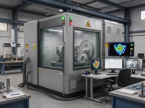
Manufactured parts can look flawless while pores, cracks, voids, or assembly errors remain hidden beneath their surfaces. Industrial computed tomography uses X-rays to create a three-dimensional record of internal and external geometry without cutting the part open. Engineers can then inspect material density, dimensions, and interfaces in one dataset. That evidence supports faster decisions during quality control, failure analysis, and product development. The scanning process becomes clearer when its imaging principles and inspection uses are examined.
Before inspection begins, engineers define the defect question, part material, expected tolerances, and required reporting format. This preparation determines whether the study emphasizes porosity, dimensional accuracy, wall thickness, or assembled fit within a working assembly. The industrial computed tomography testing method connects that planning stage with a non-destructive method that records hidden geometry, density changes, and assembly relationships. The scan can preserve the sample for additional tests while producing evidence for design, manufacturing, or supplier decisions.
How X-rays Build a 3D Record
An industrial CT scanner rotates a part through a series of X-ray exposures. Dense material absorbs more radiation than open space, so each image records variations along the beam path. Reconstruction software takes those projections and turns them into a volumetric dataset made of voxels, or three-dimensional pixels.
Each voxel carries a gray value linked to material density and position. Engineers can view the part as a complete volume and create virtual slices at any orientation. This approach reveals internal features that line-of-sight tools cannot reach, including enclosed channels, intersecting holes, bonded interfaces, and subsurface defects.

Defects That CT Scanning Finds
Porosity appears as isolated or clustered voids inside cast, molded, or additively manufactured parts. The dataset shows each void’s location, size, and relationship to nearby walls, giving engineers evidence for process correction or acceptance decisions. Cracks create narrow density changes that require careful image review and suitable resolution.
Inclusions, delamination, incomplete fusion, and trapped foreign material also appear when their density differs from the surrounding structure. CT inspection can expose shrinkage cavities in castings, unfilled regions in printed parts, and solder or component issues inside electronic assemblies. These findings support failure analysis without destroying the evidence.
Measuring Geometry Inside Assemblies
CT data supports dimensional inspection because the reconstructed volume contains surfaces that physical probes cannot contact. Engineers can compare those surfaces with a computer-aided design model, nominal dimensions, or geometric tolerances. Measurements can include wall thickness, concentricity, gap size, hole position, and internal passage shape. The same dataset records external dimensions, so internal and external results share one coordinate system.
Assemblies receive similar treatment. Virtual separation allows an analyst to inspect individual components in their installed condition, check interference, and evaluate compressed seals or hidden joints without disassembly. That preserves the original relationship between parts during analysis.
Choosing Resolution and Scan Setup
Scan planning determines whether a hidden flaw appears clearly or blends into surrounding material. Part size, density, wall thickness, geometry, and the smallest defect of interest all affect that decision. Dense metals require different exposure settings than plastics or delicate electronics. High-aspect-ratio components, such as wide printed circuit boards, can require specialized acquisition approaches.
The scan also needs enough spatial resolution to separate adjacent features without creating excessive image noise. Engineers should define the inspection question before scanning and select magnification, energy, orientation, and reconstruction accordingly. A clear requirement produces a focused dataset and a report that connects findings to acceptance criteria.
From Scan Data to Engineering Decisions
Raw volume data becomes useful when inspection criteria guide the review. Analysts can segment materials, isolate voids, calculate volumes, and map defect positions against functional surfaces. Color maps make deviation patterns visible, while slice views provide direct evidence at selected locations.
A report should identify the scanned part, state the inspection method, record relevant settings, and distinguish measured results from interpretation. Screenshots, annotated sections, and measurement tables help production teams trace each finding to a physical feature. When a defect affects performance, engineers can combine CT evidence with material knowledge, process records, or targeted follow-up tests. The result is a documented basis for containment, redesign, supplier discussion, or release before production changes are approved.
Conclusion
Industrial CT scanning changes internal inspection from an uncertain teardown into a measurable review of the complete part. Its voxel data exposes defects, verifies dimensions, and preserves assembled relationships for later analysis. The best results begin with a defined defect question, suitable scan settings, and acceptance criteria agreed before acquisition. Engineers evaluating a failure should start by selecting parts, documenting locations, and requesting a report that connects each finding to a feature and production action.
Disclaimer
Artificial Intelligence Disclosure & Legal Disclaimer
AI Content Policy.
To provide our readers with timely and comprehensive coverage, South Florida Reporter uses artificial intelligence (AI) to assist in producing certain articles and visual content.
Articles: AI may be used to assist in research, structural drafting, or data analysis. All AI-assisted text is reviewed and edited by our team to ensure accuracy and adherence to our editorial standards.
Images: Any imagery generated or significantly altered by AI is clearly marked with a disclaimer or watermark to distinguish it from traditional photography or editorial illustrations.
General Disclaimer
The information contained in South Florida Reporter is for general information purposes only.
South Florida Reporter assumes no responsibility for errors or omissions in the contents of the Service. In no event shall South Florida Reporter be liable for any special, direct, indirect, consequential, or incidental damages or any damages whatsoever, whether in an action of contract, negligence or other tort, arising out of or in connection with the use of the Service or the contents of the Service.
The Company reserves the right to make additions, deletions, or modifications to the contents of the Service at any time without prior notice. The Company does not warrant that the Service is free of viruses or other harmful components.